The Future of Maritime Travel: The Next Phase in Ship Design Evolution
Abstract
Today’s ship designers face a multitude of challenges, from meeting strict emissions regulations to optimising efficiency and engine power while ensuring future-proof propulsion solutions. Even before a vessel hits the water, its design must meet a complex matrix of parameters and pre-defined design criteria.
Fortunately, designers have more tools at their disposal than ever before. With the latest advancements in AI, neural networks are able to predict flow fields and scalar quantities in real-time. By leveraging existing simulation data, ship designers can now develop new products faster and more efficiently than ever before.
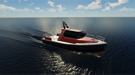
A pilot boat was developed as part of a European R&D project (Figure 1). CAESES was employed to create fully- parametric models of both the bare hull and tunnels. Simcenter STAR-CCM+ was coupled to CAESES and applied for free-surface RANS simulations at planing mode, including propellers via actuator discs. Results from a design-of-experiment (DoE) for 18 geometric parameters were taken as input to train a machine learning (ML) model for rapid design processes on both integral quantities and flow fields.
In this blog, we will give an overview of the project and explain the creation of the Reduced-Order Model (ROM), its accuracy, and other outcomes.
The International Maritime Organization (IMO) has set a target for all new ships to be 30% more efficient by 2025. This means that ship designers and engineers must focus on developing new technologies and designs that optimise efficiency while maintaining safety and meeting regulatory standards.
The Challenge
One of the most important aspects of ship design is the shape of the hull. The design of ship hull forms is crucial to reducing ship resistance and improving efficiency. Classical numerical tools like Computational fluid dynamics (CFD) can be used to evaluate hydrodynamic performance and modify hull forms. With the rise of high-performance computing (HPC), the cost of conducting high-fidelity simulations has become more affordable, making it easier for ship designers to optimise their designs.
Trade-off analyses like the one we showcase in this blog make it more difficult to balance competing objectives. Engineers must consider factors such as speed, range, fuel efficiency, and cargo capacity to develop a design that meets all requirements.
To achieve the IMO’s target, ship designers must also understand how changes in hull form can affect overall performance and operational costs. This involves developing an accurate understanding of ship performance and making trade-offs between competing objectives. One approach to achieving this is to use multi-objective optimization algorithms that can automatically explore the design space and identify designs that meet specific criteria.
Ship design plays a crucial role in reducing emissions and improving efficiency in the maritime industry. By leveraging the latest Machine learning methods and optimising hull form design, ship designers can create vessels that meet the IMO’s target, balance competing objectives, accelerate product development to ultimately reduce time-to-market. The rise of AI promises to make ship design even more efficient and environmentally friendly in the years to come.
Case Study – AI for the Design of a Planing Boat
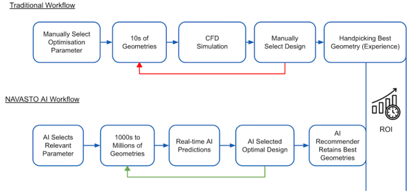
Maritime engineering projects involve complex design considerations that require coordination between different disciplines such as hydrostatics and stability, hydrodynamics and power consumption, structural engineering and safety and economics. Traditional design processes often involve delays in decision making due to time consuming serial iterations and challenges in integrating inputs from various disciplines. This can be overcome by surrogates within design synthesis, enabling to run comprehensive simulation-driven design campaigns, e.g., Harries et al. (2019), Papanikolaou et al. (2020).
Designing maritime engineering projects involves addressing complex design considerations, which necessitate collaboration between various disciplines such as hydrostatics, hydrodynamics, power consumption, structural engineering, safety and many more.
Traditional design processes frequently encounter delays in decision-making due to the time-consuming nature of iterative processes and difficulties in integrating inputs from different disciplines. However, the use of surrogates within design synthesis can help overcome these obstacles, allowing for comprehensive simulation-driven design campaigns to be conducted, as demonstrated in studies such as Harries et al. (2019) and Papanikolaou et al. (2020).
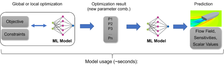
For this study, a Reduced-Order Model (ROM) is trained using simulation data obtained from the Design of Experiment (DoE), enabling the real-time prediction of new geometries, flow fields, and scalar performance values.
This process is typically divided into two phases – an offline phase and an online phase. In the offline phase, the necessary number of CFD solutions are computed, and the ROM is created, which may take a considerable amount of time depending on the use case, the number of CFD solutions, and the degree of parallelization as described earlier. During the online phase, the ROM is utilised to provide flow field predictions for a previously unknown combination of parameters within a fraction of a second, providing numerous benefits.
In this use case, the complete Design-of-Experiment was utilised for the training of the ML model and several new variants were subsequently simulated for evaluation.
By using simulation data to train a Reduced-Order Model, engineers and designers can speed-up design processes and even facilitate interactive design between different disciplines. Fast and accurate predictions of flow fields and geometries enable rapid decision making interactively without any need to postpone to the next meeting, allowing for many iterations on the fly.
These capabilities of machine learning models can result in more efficient and optimised product designs, leading to improved performance, safety, and sustainability of maritime assets. Instead of utilising series data in a conventional way by just getting two or three outputs, say for resistance and propulsion, for a handful of inputs, design teams can produce their own series and then retrieve both numerical and visual results interactively.
Optimization – Reduced Order Model + Surrogate
For the sake of argument, the resulting ML-model from the DoE was employed to optimise the planing boat within the following design scenarios:
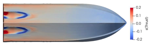
- Generate the hull with minimum thrust at 27.5 kn
- Generate the hull with minimum thrust but with a moderate pitch angle lower than 3.5° (treated as an inequality constraint)
- Generate the hull that yields minimum wave height 1m off the boat’s centre plane (at model- scale, corresponding to 3.29 m at full-scale)
In addition, some unusual configurations were also considered to understand the behaviour at further extrema:
- Generate the hull that needs maximum thrust (this, naturally, is not a common design request)
- Generate the hull that yields maximum heave
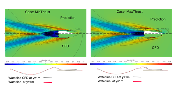
The AI predictions demonstrate a high degree of consistency between the CFD simulations and the ROM predictions of the boat. The differences observed at the bow are primarily due to the complex CFD set-up, which employs a dynamic mesh with multiple overset regions to map the running attitude in the domain. However, the ML-model used for the predictions was solely trained on the coarser background mesh and did not include the overset region near the bow.
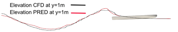
Fig.4 illustrates the comparison between the wave cuts at a transversal position situated 1m from the centre plane of the hull (measured at model-scale). The prediction and actual CFD results exhibit a good level of agreement, as depicted by the isoline for the volume fraction of air at 0.5. It is worth noting that the wave cuts have been scaled twenty times in the vertical direction to enhance their visibility.
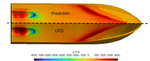
In addition, the Reduced-Order Model displays a high level of accuracy in predicting field values, such as the dynamic pressure on the hull’s wetted surface for the boat’s minimum thrust condition. The propulsion system generates complex pressure distributions due to the resulting trim and rise, which are well-captured and represented by the ML-model. It should be noted that the field values were not a part of the ROM but rather were pure predictions.
The AI predictions demonstrate a high degree of consistency between the CFD simulations and the ROM predictions of the boat. The differences observed at the bow are primarily due to the complex CFD set-up, which employs a dynamic mesh with multiple overset regions to map the running attitude in the domain. However, the ML-model used for the predictions was solely trained on the coarser background mesh and did not include the overset region near the bow.
Fig.4 illustrates the comparison between the wave cuts at a transversal position situated 1m from the centre plane of the hull (measured at model-scale). The prediction and actual CFD results exhibit a good level of agreement, as depicted by the isoline for the volume fraction of air at 0.5. It is worth noting that the wave cuts have been scaled twenty times in the vertical direction to enhance their visibility.
In addition, the Reduced-Order Model displays a high level of accuracy in predicting field values, such as the dynamic pressure on the hull’s wetted surface for the boat’s minimum thrust condition. The propulsion system generates complex pressure distributions due to the resulting trim and rise, which are well-captured and represented by the ML-model. It should be noted that the field values were not a part of the ROM but rather were pure predictions.
Digital Twins – The Ultimate Solution?
With the advent of more powerful computers, engineering teams are now able to develop increasingly complex and detailed digital models that replicate a product’s behaviour and characteristics with ever more precision. One such technology, the digital twin, is transforming the way products are designed, operated, and maintained across a broad range of industries.
Generative design and optimization methods rely on computer simulations to find the most optimal solution for a given design problem. By running multiple simulations and making iterative tweaks to the design, these approaches can often outperform even the most skilled human designers in terms of creating efficient and effective designs.
Oftentimes, it is just impossible for a designer or engineer to go through all the possible design scenarios because of the time or the limitation of designers’ experience.
Although digital design optimization shows promise, it also has notable limitations. The performance of structures or fluid flows is simulated using computationally intensive differential-equation solvers, which restricts design optimization to only few simultaneous parameters. Consequently, current systems only explore a small portion of the design space and yield modest improvements.
Due to these constraints, companies still heavily rely on human engineering expertise to select and optimise project parameters, which is challenging when skilled professionals are scarce. Additionally, the complexity of simulation systems means that businesses often turn to external providers to run their simulations, which erodes in-house knowledge and proficiency and increases the risk of suboptimal designs resulting from human bias.
In a world where both speed and innovation are critical to maintaining a competitive advantage, relying solely on traditional simulation approaches may not suffice. Engineering companies must consider alternative approaches to design optimization and the technologies they utilise to achieve it.
Conclusion & Outlook
The design of a planing boat was approached through a combination of parametric modelling, CFD simulations, Design-of-Experiment, and machine learning. A significant number of variants were analysed based on high-fidelity CFD simulations utilising Simcenter STAR-CCM+, and their quality was validated by comparing them to experimental data.
Several new designs were generated by applying the ROM. These designs are representative of meaningful design situations. They also served to judge the quality of the ROM. For thrust differences between predictions and CFD simulations range within ±5.2% of the CFD results taken as the benchmark. Thrust as the driver for the optimization of the pilot boat was predicted from the ROM with an error of about -0.4% when studied for an optimised design that had been previously identified within a sophisticated SDD campaign. Moreover, it turns out that there are very nice correlations for wave fields and pressure field, too. Keeping in mind that optimizations often lie at some of the bounds of the free variables and that 89 variants is not a very large set of variants for an 18-dimensional design space to begin with, these are believed to be very encouraging results.
The parameters, resulting shapes, and their corresponding flow fields were analysed, along with integral results such as the thrust required to run each of the variants at 27.5kn, and used to build a Reduced-Order Model using NAVPACK.
The utilisation of Machine learning in product development is still in its early stages but leading companies such as Audi, Airbus, Lamborghini and Volkswagen are now integrating AI into their engineering processes for various product categories and use cases.
One potential game-changing approach involves drastically reducing traditional simulation methods. Instead, Machine learning models can be trained using (historic) simulation data obtained from existing products in the field and predict unseen scenarios in a matter of seconds. This will revolutionise the way companies improve their products, as design and optimization tools learn automatically from the performance of previous product generations.
We would like to take this opportunity to thank Stefan Harries (Friendship Systems) and Osama Ahmed (Imperial College London) for their contribution to this article.
Explore the potential and possibilities of AI-Accelerated Engineering here and do not hesitate to contact us to talk about your use case!